Table of Contents
Introduction
In this tutorial we will learn how to interface joystick module with Raspberry Pi Pico board and observe the output. It is a basic analog and digital input interfacing of Raspberry Pi Pico board. The joystick is connected to two potentiometer for the x and y axis analog reading and a push to on switch in the middle of the joystick. So, when we press the joystick the an input signal is provided to the Raspberry Pi Pico. We can use this push button carry out any of our task.
Hardware Requirements
Disclaimer: It may contains Amazon affiliate links. which means I can get a small commission on the sale. This might be your indirect help to me. Thank You 🙏- Raspberry Pi Pico Board (HERE)
- Micro-USB Cable (HERE)
- PS2 Joystick (HERE)
- Small Breadboard (HERE)
- Connecting Wires (HERE)
Software Requirements
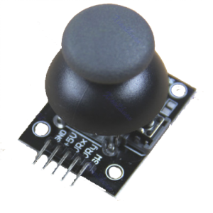
About PS2 Joystick
This joystick is a two axis joystick with a center button, this module have two potentiometer connected to read the analog value for x-axis and for y-axis. The two potentiometer is placed in such a way that when we move the joystick from right to left or left to right the x-axis potentiometer value changes and when we move from top to bottom or bottom to top the y-axis value changes. And a switch is connected at the center of the joystick handle. So, that we can press the handle to ON the switch.
- +5v: Here we need to supply voltage
- GND: Need to connect with the common ground of the circuit
- VRx: The x-axis analog value changes with the change in the x-axis movement of joystick.
- VRy: The y-axis analog value changes with the change in the y-axis movement of joystick.
- SW: The switch need to connect with any digital input pin to read the data and respond accordingly.
Circuit Diagram
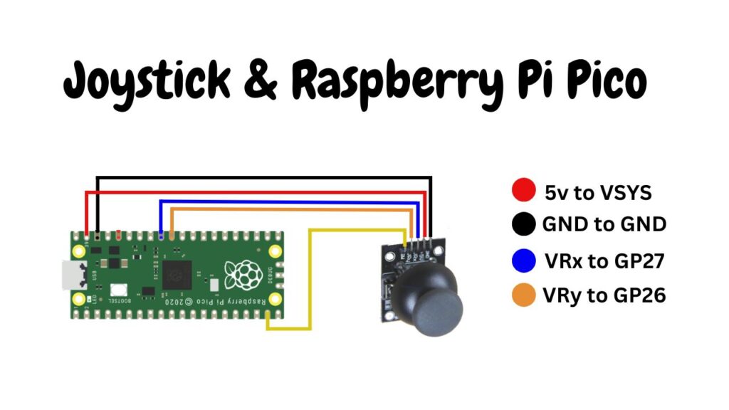
Circuit Explanation
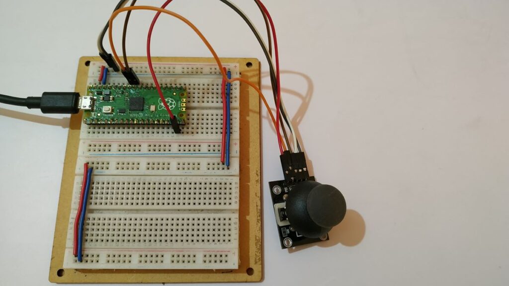
The above circuit diagram is very easy to understand and you can see that the PS2 joystick is connected directly. Follow the connection table below and build the circuit.
| PS2 Joystick | Raspberry Pi Pico |
| VCC | 5v |
| GND | Ground |
| VRx | GP27 |
| VRy | GP26 |
| SW | GP14 |
Source Code
The code is written in MicroPython. The sensor data is fetched from the joystick and display it on serial monitor
Main Code: (main.py)
Now create one file in the Thonny IDE and copy/paste the code given in the download section as joyStickInterfacing.txt and save it as a main.py file in the Raspberry Pi Pico board.
from machine import Pin, ADC
import utime

xAxis = ADC(Pin(27))
yAxis = ADC(Pin(26))
button = Pin(14,Pin.IN, Pin.PULL_UP)

while True:
    xValue = xAxis.read_u16()
    yValue = yAxis.read_u16()
    if button.value() == 0:
        buttonStatus = "Pressed"
    else:
        buttonStatus = "Not Pressed"

    print("X= " + str(xValue) + ", Y= " + str(yValue) + " button status: " + buttonStatus)
    utime.sleep(0.5)
Why the main.py file name?
You can give any name to the file but when running the code from Thonny IDE by clicking the green button it will run once. But when we give the name main.py to the file, the Raspberry Pi Pico board will automatically detect and run the code whenever you want. You can say that this is a process of AutoStart system.
Video Tutorial
Download Source Code
Download the complete source code: click here