Table of Contents
Introduction
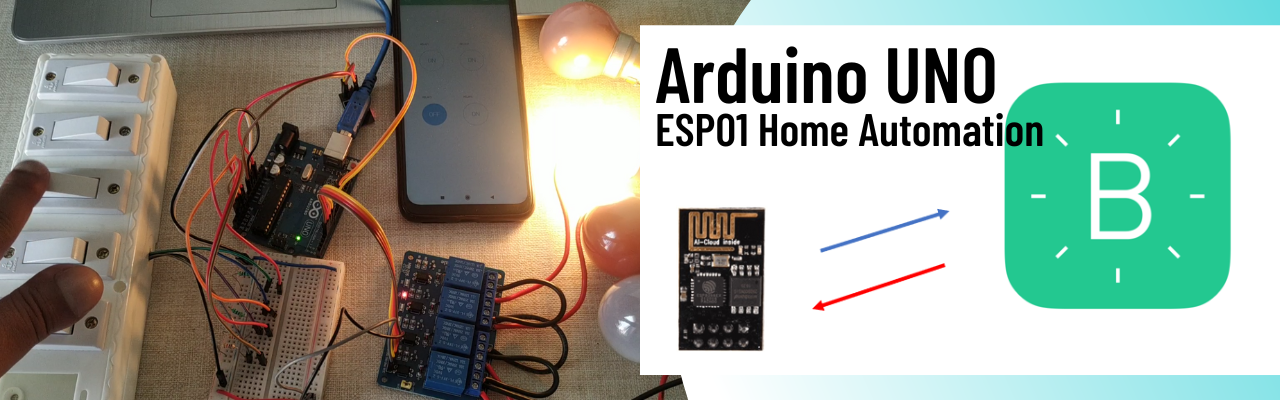
In this project we will learn about the project Home Automation using Arduino UNO, ESP8266-01 module and Blynk mobile application. This is most common and popular project among the hobbyist and school/college students. Home automation means we will control the home appliances over the internet using Blynk application.
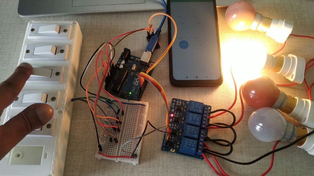
The best part of this project is, this project has dual functionality with which you can control the home appliances using manual switches and also using Blynk mobile app over the internet. In this project we will demonstrate controlling of four bulbs, but you can connect any appliance which operating voltage is 220/240v AC 50Hz as most of the home appliances works on it.
You can check our projects on Home Automation before you want to build this project.
- Home Automation using NodeMCU and Firebase
- Google Assistance based Home Automation using Arduino
- Bluetooth based Home Automation
- Voice Controlled Home Automation
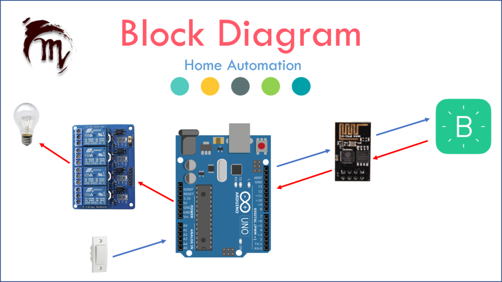
In this article a Arduino UNO is connected with an ESP8266-01 module for the internet. A relay driver is connected also connected to the Arduino UNO board which control the devices over the Arduino UNO commands which is being connected to the Blynk application over the internet.
Hardware Requirements
Disclaimer: It may contains Amazon affiliate links. which means I can get a small commission on the sale. This might be your indirect help to me. Thank You 🙏- Arduino UNO (HERE)
- ESP8266-01 Module (HERE)
- 4-Channel Relay Driver (HERE)
- Connecting Wires (HERE)
- Breadboard (HERE)
- AC bulb holder
- AC bulb
- Connecting wire for AC lines
Software Requirements
Block Diagram
Circuit Diagram

Circuit Explanation
According to the above circuit diagram, the major components of the circuit are:
- Arduino UNO
- Power Supply
- WIFI Module ESP8266-01
- Relay and relay drivers
Arduino UNO Circuit
Main logic decision-making takes place over here. The Arduino UNO board is connected to the ESP module and Relay with Relay drivers. ESP8266-01 is the most important part of the circuit. Should be connected in a proper manner to transmit and receive data.
| ESP8266-01 | Arduino UNO |
| Rx and Tx | Pin11 (Tx) and Pin12 (Rx) respectively |
| CH_PD and Vcc | 3.3v |
| GND | GND |
Power Supply
Power supply is provided by Arduino UNO connected to the laptop, but if you want to connect an external power supply to make the project standalone you can refer to the article Google assistance based home automation to find the external power supply circuit diagram and connection details.
Relay and Relay Drivers
When a key gets confirmed the respective pin becomes HIGH and due to this HIGH LEVEL or 5v it triggers the transistor BC547 connected with a resister to its base, the emitter is grounded and the collector of this BC547 is connected to the one end of the coil of 12v relay. So, when the transistor gets a voltage more than the voltage of the base emitter it triggers the transistor making the current flow from the collector to the emitter. And provides a ground to the relay circuit and the relay starts operating. This means the COMM point of relay switches to NO from the NC point. NO is connected with the NEUTRAL point of the AC supply and PHASE is provided to the device initially. So, whenever the COMM point switches to NO from NC, COMM provides NEUTRAL to the device. And the device or any appliances or bulb connected to it gets ON.
How to setup Blynk Mobile Application
To setup your Blynk mobile for this project you can follow the video tutorial or you can click on this tutorial to learn more.
Home Automation Setup
Video Tutorial
Download Source Code
Download the complete source code: click here