Table of Contents
Introduction
In this tutorial, you will learn how to integrate NodeMCU with the DHT11 sensor and fetch the sensor data, and send the data to the Adafruit IO IoT platform. In this way, you can also monitor the sensor data.
This is our first tutorial on the Adafruit IO an IoT platform. So, you will learn from the basics of the platform which includes how to create a free account, then creating the feed, and then create the dashboards which are your sensor data monitoring platform. And again on the hardware side, you will learn how to install libraries like Adafruit MQTT Library, and DHT11 sensor Library by Adafruit. If you want to add an OLED display you can follow any OLED display tutorial on our blog website and copy and paste the code into this project.
About Adafruit IO
Adafruit IO is an IOT platform that supports MQTT data protocol which is the faster way of data communication with the cloud-based system from HTTPS data protocol. A wide range of platforms and devices, including embedded systems, smartphones, and cloud platforms, support MQTT. IoT applications, such as home automation, industrial monitoring, and smart cities, widely use MQTT. Its lightweight nature, flexibility, and scalability contribute to its popularity, making it ideal for various IoT scenarios. MQTT supports three levels of QoS (Quality of Services) which determines the data delivery rate.
Adafruit provides an easy-to-build dashboard area to display sensor data and more. Adafruit offers a wide range of displays, known as Blocks, which can display various types of data. These Blocks can also control IoT devices.
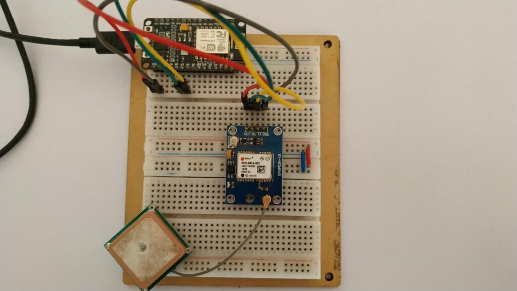
In this tutorial, we will use NodeMCU to connect a NEO 6M GPS module to get the location data, and using wifi connectivity the data will be sent to the Adafruit IO platform. You can check the location data on the dashboard that you have created for the data display.
Hardware Requirements
Disclaimer: It may contains Amazon affiliate links. which means I can get a small commission on the sale. This might be your indirect help to me. Thank You 🙏Software Requirements
- Arduino IDE (You can download it from HERE)
- Install all libraries carefully (Follow the youtube tutorial HERE)
- Adafruit IO account
How to create an Adafruit IO account
To create an account go to the official website of Adafruit IO. You can also follow our YouTube tutorial to learn or you can follow this article as shown below.
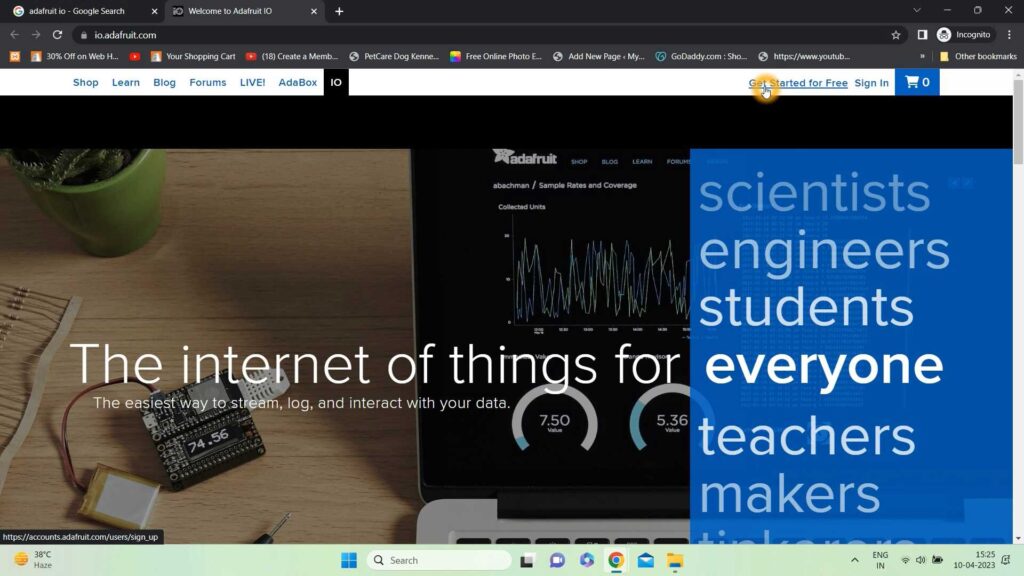
Go to the Adafruit IO website and click on Get Started for Free at the top right corner.
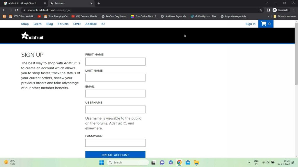
Now in order to create and free account you need to enter the required details. After entering the details click on CREATE ACCOUNT to create your account.
After clicking on Create Account an account your free account will be created. Now just sign in to your account and click on IO at the top of the page to create a dashboard and feed to display the location data.

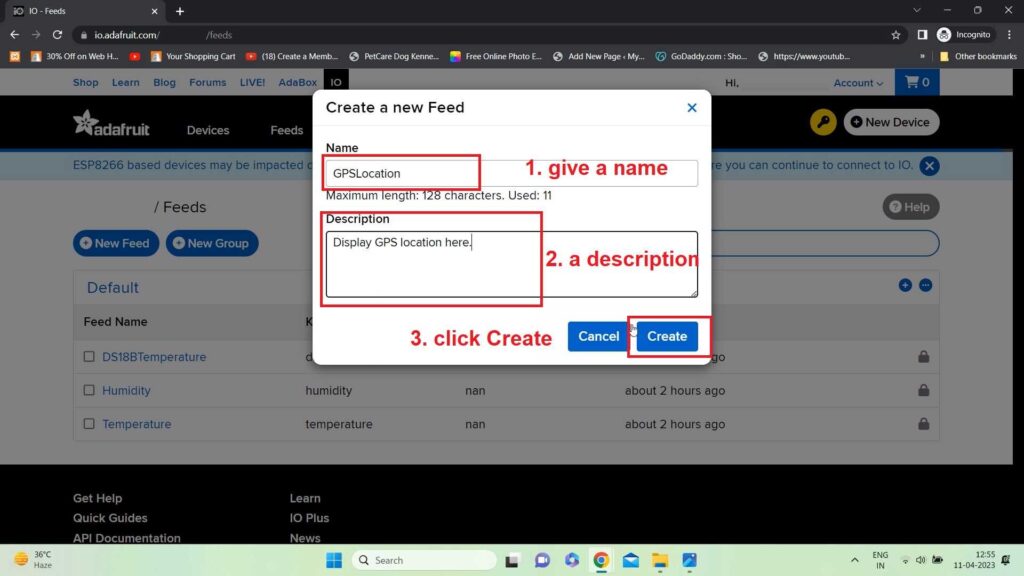
Now click on Feeds to create a Feed. Feed is nothing but a variable name that you will subscribe to this feed and can read/write data to it. So, to create a feed click on Feeds at the top and then click on Create the feed. A popup window will open you need to provide the name and a description to the feed and then click on Create.
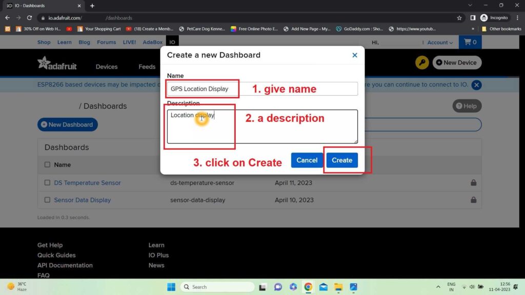
Now to create a Dashboard, click on the Dashboards tab at the top of the page. Again just like the feed you need to click Create Dashboard and a popup window will open where you need to provide the details of the dashboard like name and description.
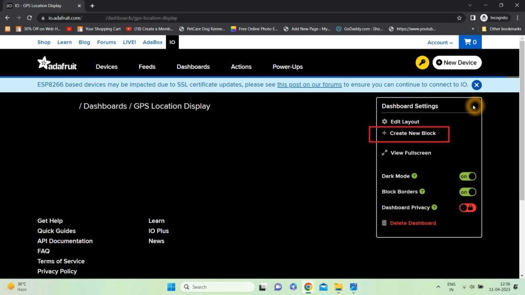
Now after creating a feed as GPSLocation and a dashboard as GPS Location Display you need to connect the feed to the dashboard. So, that you can see the data on the dashboard.
So, to connect the feed with the dashboard you need to create a Block in the dashboard.
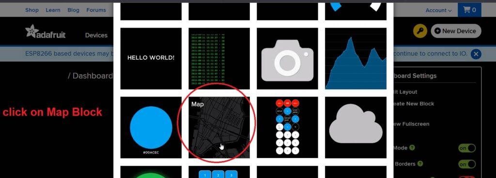
Now you can see that you have different blocks. You use it as per your requirement, but here I am using GPS so, I will choose Map Block to display the location.
After clicking on the Map block you will get a popup window to set up the Feed or you need to connect with the feed you have created. Our feed name is GPSLocation so we will connect with it.
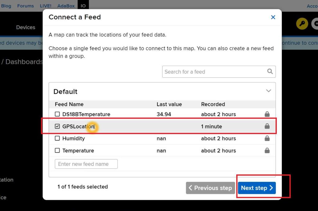
Then click on the Next step to set up the layout of the block. Here just give a name to your layout and set up the Light and Dark modes of Map visual.
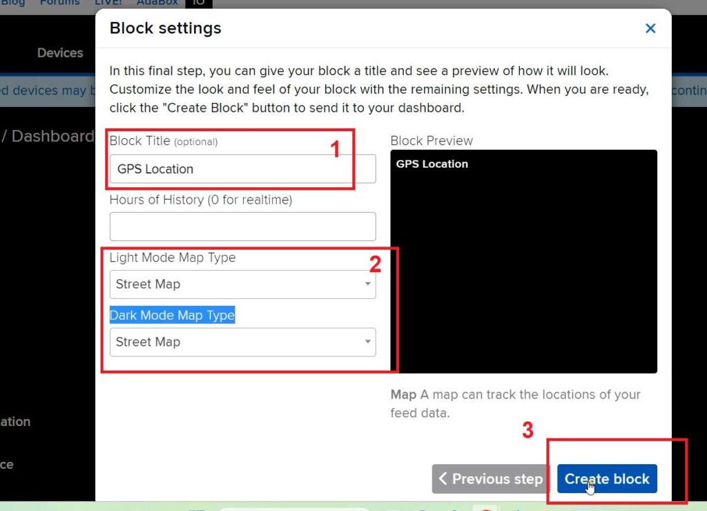
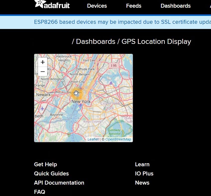
After clicking on the Create block you will be redirected to a dashboard with the map visual and can set the map.
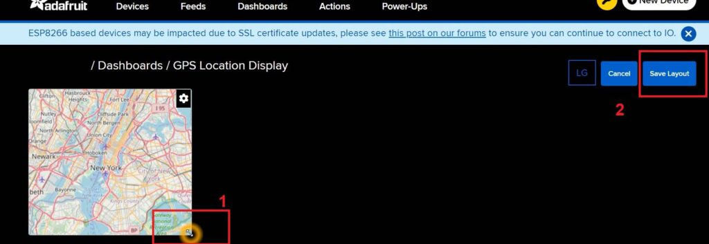
Now if you want to resize the map you can click on the setting icon and then click Edit Layout. Now you can resize the layout by just clicking and holding the one side map and dragging the map to resize and clicking Save Layout to save it.
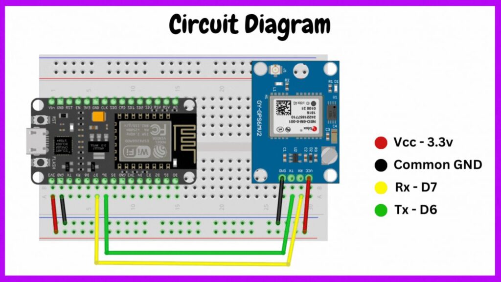
Circuit Diagram
Circuit Explanation
According to the above circuit diagram, the major components of the circuit are:
- NodeMCU
- NEO GPS
Follow the below table to make the connection between NodeMCU and GPS. The Tx and Rx connect properly as this is an important part of the project.
| NEO 6M GPS | NodeMCU |
| Rx and Tx | D7 (Tx) and D6 (Rx) respectively |
| Vcc | 3.3v |
| GND | GND |
Power Supply
The power supply is given by the USB cable itself from the laptop. But, you can create a 5v external power supply and connect it to Vin and GND of NodeMCU board.
NodeMCU and GPS setup
Video Tutorial
Download Source Code
Download the complete source code: click here