Table of Contents
Introduction
In this article, we will learn how to create a web server using ESP32 from scratch. We will go through the step-wise process of connecting ESP32 with the relay driver and creating a web application for the user to control the relays or the devices connected to the relays.
For the web application, we will use Bootstrap as our building base, as this framework is easy to understand and easy to integrate from the basic conventional HTML and CSS pages. So, for the UI side code, we will develop it in Bootstrap.
How does it work?
After turning on the ESP32 module the default WIFI credentials will try to connect with the network, So after the connection ESP32 we provide us a local IP address in the serial monitor and then we will use IP address by copy and pasting it in any of our favorite browser. Then ESP32 will detect the new connection and a web page designed in bootstrap will be shown with multiple buttons. So, when the user clicks the button the relay will turn ON or OFF as per previous status.
This project is built on ESP32 microcontroller which will serve a web page on request from client. The client may be a computer, a mobile device or any device which is capable to run browser engine.
The ESP32 controller is connected to a 5v 4 channel relay which can control four devices at any point of time. We will understand the source code and can be downloaded from the download section.
Hardware Requirements
Disclaimer: It may contains Amazon affiliate links. which means I can get a small commission on the sale. This might be your indirect help to me. Thank You 🙏Software Requirements
ESP Board Manager Link
https://dl.espressif.com/dl/package_esp32_index.json
http://arduino.esp8266.com/stable/package_esp8266com_index.json
About 5v Relay

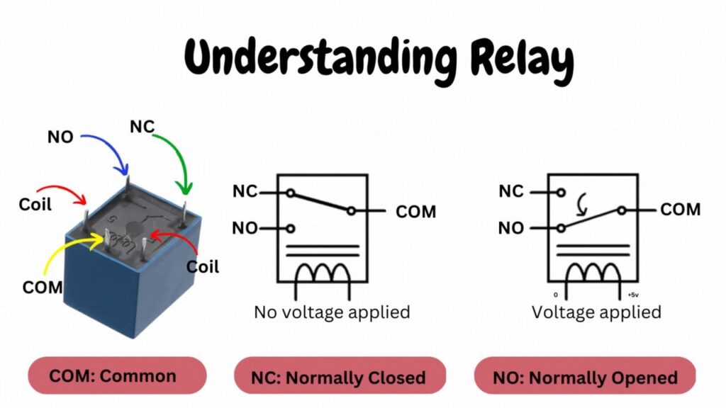
A 5V mechanical switching relay is an electromechanical device that allows you to switch on/off electrical circuits using a low-voltage control signal. A coil generates an electromagnetic force that operates a switch, which consists of the coil and a set of contacts.
When we provide proper voltage at the coil terminal, the contact connected at NC normally connected point is shifted to the NO normally open point. And then completing the whole circuit. This mechanical switching uses a digital signal using an optocoupler in the 5v relay module.
About ESP32
ESP32 is a low-cost, low-power, and powerful microcontroller. ESP microcontroller, which is based on the Xtensa LX6 processor. It is widely used in embedded systems and Internet of Things applications. You can develop a number of projects or application because of its versatility. Some of the important features are listed below.
- It has dual core processor that can be program and controlled independently, Which is the best part for multi tasking at the same time.
- ESP32 has Wi-Fi and Bluetooth dual wireless connectivity, which make best option for IoT application that require wireless connectivity.
- It has various power-saving modes, which can extend the battery life in a battery powered application.
- ESP can be programmed using C, C++, and MicroPython.
You can use the ESP32 board as either a server or a client in a network. As a server, the ESP32 listens to incoming requests from clients. As a client, it sends requests to the server and exchanges data.
So, after connecting with the network ESP32 hostname is the IP address that is assigned to the ESP32 or the default name “Espressif”.
About Bootstrap
Bootstrap, is a popular front-end web development framework. This open-source framework offers various built-in components, including HTML, CSS, and JavaScript, which developers can use to create responsive web and mobile pages and applications.
Bootstrap makes easy for the developers to develop a consistent and best user interface, without writing a custom CSS and JavaScript, which reduces the development time and effort while creating web applications
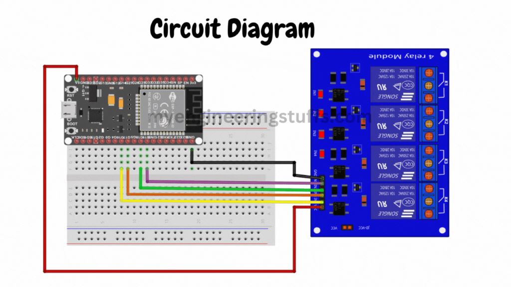
Circuit Diagram

Circuit Explanation
Follow the circuit diagram and build your circuit correctly.
Relay Driver: The relay driver I am using is a 5v 4-channel relay, this means I can control up to 4 devices. The circuit diagram is explained in the below table.
| Relay Driver | Raspberry Pi Pico |
| VCC | Common 5v |
| GND | Common GND |
| IN1 | GP16 |
| IN2 | GP17 |
| IN4 | GP18 |
| IN4 | GP19 |
Source Code Explanation
// Replace with your WIFI credentials
const char* SSID_NAME = "REPLACE_YOUR_SSID";
const char* SSID_PASSWORD = "REPLACE_YOUR_SSID_PASSWORD";
Status of the relay updated in this variables.
String relay16Status = "off";
String relay17Status = "off";
String relay18Status = "off";
String relay19Status = "off";
Relay is connected to the variables assigned.
const int relay16 = 16;
const int relay17 = 17;
const int relay18 = 18;
const int relay19 = 19;
Video Tutorial
Download Source Code
Download the complete source code: click here