Table of Contents
Introduction
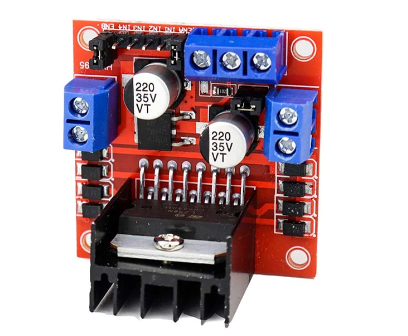
The L298N is a dual full-bridge motor driver IC. It can control the speed and direction of two DC motors or one stepper motor. It uses H-bridge circuitry, which allows for bidirectional control of the motors. The IC has two enable pins (IN1 and IN2), which can be used to control the speed and direction of the motors. It also has built-in protection against overheating and overcurrent, which helps to protect the IC and the motors. The L298N can be controlled using a microcontroller, such as an Arduino.
How it works?
The L298N motor driver IC uses H-bridge circuitry to control the speed and direction of DC motors or a stepper motor. An H-bridge is an electronic circuit that allows a voltage to be applied across a load in either direction. This means that the L298N can control the speed and direction of the motor by applying a voltage to different combinations of its input pins.
The L298N has two enable pins (IN1 and IN2) for each motor, and these pins are used to control the speed and direction of the motor. By applying different combinations of voltage to the input pins, the L298N can control the motor to rotate in either direction or stop.
For example, to make the motor rotate in a clockwise direction, the voltage would be applied to the IN1 pin and ground to the IN2 pin. To make the motor rotate in a counterclockwise direction, the voltage would be applied to the IN2 pin and ground to the IN1 pin. To stop the motor, both IN1 and IN2 pins would be at the same level (either both high or both low).
The L298N also has built-in protection against overheating and overcurrent to protect the IC and the motors. It can handle a maximum current of 2A per channel and up to 36V.
It is controlled by a microcontroller such as an Arduino, which sends commands to the L298N to control the motor speed and direction.
Basic Connection Diagram:

Basic Arduino Code to run Single Motor
Here is an example of Arduino code that can be used to control a DC motor using the L298N motor driver:

const int enA = 9;   // Enable A pin
const int in1 = 8;   // Input 1 pin
const int in2 = 7;   // Input 2 pin

void setup() {

  pinMode(enA, OUTPUT);
  pinMode(in1, OUTPUT);
  pinMode(in2, OUTPUT);

}

void loop() {
  // rotate clockwise at full speed
  digitalWrite(in1, HIGH);
  digitalWrite(in2, LOW);
  digitalWrite(enA, HIGH);
  delay(3000);

  // rotate counter-clockwise at half speed
  digitalWrite(in1, LOW);
  digitalWrite(in2, HIGH);
  analogWrite(enA, 128); // PWM value of 128 = 50% duty cycle
  delay(3000);

  // stop the motor
  digitalWrite(in1, LOW);
  digitalWrite(in2, LOW);
  digitalWrite(enA, LOW);
  delay(3000);

}
Code Explanation:
This code sets the IN1 and IN2 pins to control the direction of the motor and the EN pin to control the speed. The setup function sets the pin modes for the three control pins. The loop function rotates the motor clockwise at full speed for 3 seconds, then counter-clockwise at half speed for 3 seconds, and finally stops the motor for 3 seconds.
It’s important to note that this code is just an example, and the specific details of how you control your motor will depend on your application and the specific motor you are using.