Table of Contents
Introduction
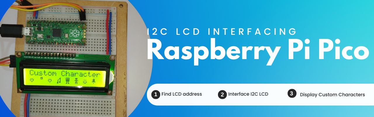
In this tutorial we will learn how to interface an I2C alpha numeric 16×2 LCD with Raspberry Pi Pico board. We will start with finding the I2C LCD address then we will display the LCD using different displaying command and then we will display the custom character.
Display text is the basic part on any device user interface. So, to display user interface messages we need to use LCD on the device, but when we have limited interfacing GPIOs we should use I2C protocol to interface.
Material Requirements
Disclaimer: It may contains Amazon affiliate links. which means I can get a small commission on the sale. This might be your indirect help to me. Thank You 🙏- Raspberry Pi Pico Board (HERE)
- Micro-USB Cable (HERE)
- I2C Module (HERE)
- 16×2 LCD Module (HERE)
- Small Breadboard (HERE)
- Connecting Wires (HERE)
Software Requirements
- Thonny IDE (Download HERE)
- findLCD code
- lcd api (LCD Library)
- pico_i2c_lcd (I2C LCD Library)
- LCD Test Code
- Custom Character Code (Download HERE)
About 16×2 Alphanumeric LCD
It is a rectangular LCD panel that can show 16 alphanumeric characters in one line and there are 2 such lines. Hence it is named 16×2 LCD. It has 16 pins. The figure below shows a 16×2 LCD with respective pins.
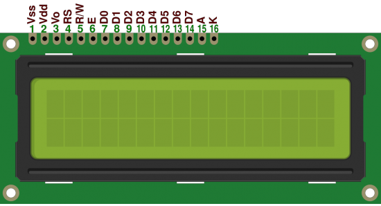
At first we initialize the LCD by selecting command registers and passing the corresponding command instructions.
At 2nd select data registers and pass corresponding data values to be shown in the display.
RS, RW, and EN are the command registers, and D0 to D7 are the data registers. Read more…
About I2C LCD Module (PCF8574P IC)
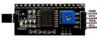
This IC is a silicon CMOS circuit. It provides general-purpose I/O expansion for most of the microcontroller families via an I2C bus. The device consists of an 8-bit quasi-bidirectional port and an I2C bus interface. The IC has low current consumption and includes latched outputs with high current drive capability. It has three addressing pins pin1, pin2, and pin3 are responsible to set the address. Follow the below table to set the address as per your requirement. The below image represents the pin diagram of I2C LCD module.
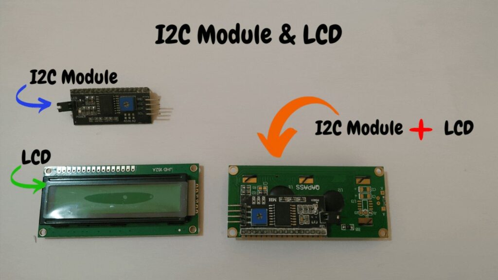
Now when we connect the I2C LCD module with the LCD, we have the I2C LCD which can used to display user information using I2C protocol.
Circuit Diagram
Circuit Explanation
The above circuit diagram is very easy to understand and you can see that the PS2 joystick is connected directly. Follow the connection table below and build the circuit.
| I2C LCD | Raspberry Pi Pico |
| VCC | 5v |
| GND | Ground |
| SCL | GP17 |
| SDA | GP16 |
Source Code Explanation
MicroPython Code: The code we are using here is a composition of mainly five parts.
- findLCD code (Download HERE)
- lcd_api (LCD Library)
- pico_i2c_lcd (I2C LCD Library)
- LCD Test Code
- Custom Character Code (Download HERE)
Download the code from the download section. After completion of the circuit open Thonny IDE and follow the below steps to get the code working.
findLCD code:
Now create a new file in Thonny IDE and open the findLCD.txt file and copy the code to the new file and save it as a findLCD.py file in the Raspberry Pi Pico board. And run the file you can see the address of the LCD in the serial monitor. This address will be used in further process, note down the address.
lcd_api library code:(lcd_api.py)
Now create another new file in Thonny IDE and open the lcd_api.txt file and copy the code to the new file and save it as a lcd_api.py file in the Raspberry Pi Pico board. This is the LCD library file.
pico_i2c_lcd library code:(pico_i2c_lcd.py)
Now create another new file in Thonny IDE and open the pico_i2c_lcd.txt file and copy the code to the new file and save it as a pico_i2c_lcd.py file in the Raspberry Pi Pico board. This is the I2C LCD library file.
Now after setting up property the two library file in the raspberry pi pico board. Note: The two library file must be in the raspberry pi pico board.
LCD Test Code: Now to test the LCD display, create a new file and open the testCode.txt file and copy the code to the new file and save it anywhere you and then press the green play button to run the code. This process will start displaying the demo text message on the LCD display.
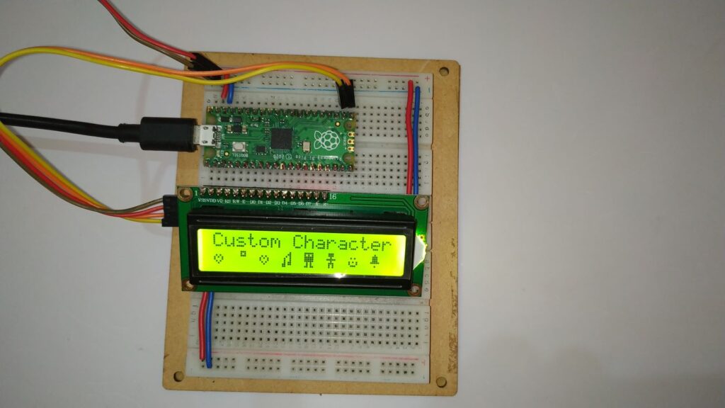
Custom Character Code: Now to display custom characters open the customCharacters.txt file copy the whole code and again create a new file in Thonny IDE and paste the code and save it anywhere you like and run the code by pressing the green play button at the top of Thonny IDE. Now you can see the custom characters on the display.
Points to Note: To run the code automatically you need to give the name main.py to the code and save it in the Raspberry Pi Pico board.
Video Tutorial
Download Source Code
Download the complete source code: click here