Table of Contents
Introduction
While interfacing LCD we have come across a problem with the pins required for any application. As you know while interfacing LCD we need RS, E, D4, D5, D6, and D7 which means we need at least 6 pins to the interface which becomes an issue when you are developing an application with more features and with fewer i/o pins of any microcontroller. In Arduino UNO we have 20 pins to utilize. If you are developing such a system that needs more pins due to your features with LCD. You must be thinking about how we can reduce the number of pin requirements. So, interfacing LCD with an I2C module is the best way to reduce pin requirements. In this tutorial, we will learn how to interface the I2C module to display on LCD and we will make our own I2C-driven LCD module using PCF8574P an 8-bit quasi-bidirectional I/O port. This IC can be used to extend GPIO using the I2C bus or I2C protocol.
In this tutorial we will use a ready-to-use I2C LCD module it is very small and easily fit your LDC module and in another part, we will design the same circuit using PCF8574P IC.
About PCF8574P IC
This IC is a silicon CMOS circuit. It provides general-purpose I/O expansion for most of the microcontroller families via an I2C bus. The device consists of an 8-bit quasi-bidirectional port and an I2C bus interface. The IC has low current consumption and includes latched outputs with high current drive capability. It has three addressing pins pin1, pin2, and pin3 are responsible to set the address. Follow the below table to set the address as per your requirement.
PCF8574P IC address

Hardware Requirements
Disclaimer: It contains Amazon affiliate links. which means I can get a small commission on the sale. This might be your indirect help to me. Thank You 🙏- Arduino UNO (HERE)
- 16×2 alphanumeric LCD (HERE)
- I2C LCD module (HERE)
- PCF8574 IC (HERE)
- 10K POT (HERE)
- Some connecting wires. (HERE)
- Small breadboard. (HERE)
Software Requirements
- Arduino IDE (You can download it from HERE).
- Arduino I2C LCD Library
- WIRE Library (Inbuilt within the IDE)
Block Diagram
As you can see the block is easy to understand. Arduino is communicating with PCF8574P IC using I2C bus. And PCF8574P IC is used to interact with LCD to work properly. Rest the library handles everything easily.

Circuit Diagram
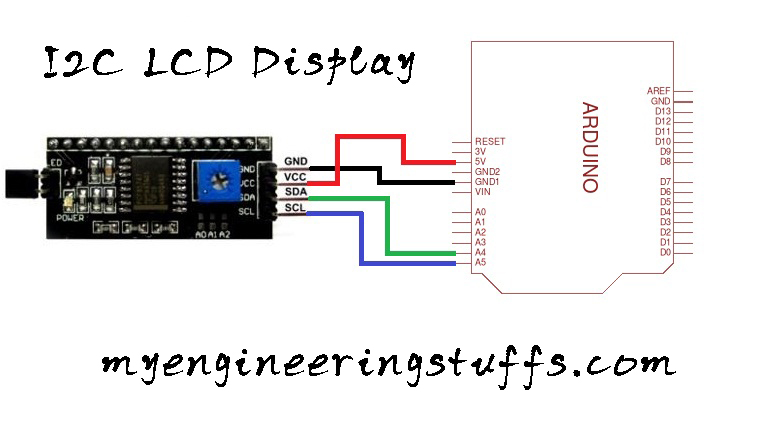
The circuit we are using for the I2C module is an easy one

The circuit we are using for PCF8574P IC

Circuit Explanation
Looking at the circuit diagram you can see that PIN numbers 15 and 16 are SDA and SCL of PC8574P IC so you need to connect these two pins to Arduino SDA and SCL pins respectively. Pin 11, 10, and 9 are connected to RS, RW, and E respectively. This pin controls the read/write process of LCD and pins 4, 5, 6, and 7 of PCF8574P IC are connected to D4, D5, D6, and D7 of LCD. Again LCD is provided with 5v DC at pins 2 and 15 similarly GND is provided with GND at pins 1 and 16. A 10K POT (variable resistor) is connected at pin 3 of the LCD which is responsible to set the contrast of the LCD.
Please follow this table of connections
| PCF8574P | 16×2 LCD |
| 1, 2, 3 and 8 | GND |
| 4, 5, 6 and 7 | D4, D5, D6, and D7 respectively |
| 11, 10 and 9 | RS, RW, and E respectively |
| 12 and 13 | Not connected |
| 14 and 15 | SDA and SCL of Arduino |
| 16 | 5v DC |
Code Explanation
The same code is applicable for both processes. As you can see we are using the same code for the I2C module and for the PCF8574P IC. First, we need to include the libraries we are going to use. The below libraries are going to use.
#include <Wire.h>
#include <LiquidCrystal_I2C.h>
We need to define an object of the LiquidCrystal_I2C constructor. Set the LCD address accordingly after looking at the table. The first parameter is to pass the I2C bus address, and the second and third include the type of LCD. As we are using a 16×2 LCD module we have passed 16, 2.
LiquidCrystal_I2C lcd(0x20,16,2); // here address of my LCD is 0x20In the SETUP function, we will initialize the LCD and turn on the backlight by passing the below code.
lcd.init();               // initialize the lcd
lcd.backlight();     // Print a message to the LCD.
Full source code
#include <Wire.h>
#include <LiquidCrystal_I2C.h>
//Address:A0-LOW,A1-LOW,A2-HIGH for PCF8574P ic
//set the LCD address to 0x20 for a 16 chars and 2 line display

LiquidCrystal_I2C lcd(0x20,16,2);

void setup()
{
  lcd.init();          // initialize the LCD
  lcd.backlight();    // Print a message to the LCD.
  lcd.setCursor(0,0);
  lcd.print("   WELCOME TO   ");
  delay(2000);
  lcd.setCursor(0,0);
  lcd.print("MY UTUBE CHANNEL");
  delay(2000);
}

void loop()
{
 lcd.setCursor(0,1);
 lcd.print("   PCF8574P IC   ");
 delay(2000);
 lcd.setCursor(0,1);
 lcd.print(" I2C LCD DISPLAY ");
 delay(2000);
}