Table of Contents
Introduction
When it comes to sorting anything we look into the color first and try to sort the things accordingly. And in case you have many items it becomes and tidy job to do. Basically, this system can be used to sort objects on the basis of their color. In this project, we will interface the color sensor TSC3200 using Arduino UNO. The sensor is made up of tiny RGB sensors which detect the amount of which part is more than the others.
About TCS3200
The sensor contains red, green, and blue color sensing matrixes which detect the intensity of red light, green light, and blue light intensity. As per the intensity of the red, green, and blue light, the sensor can be programmed to detect any particular color using a programmable filter and if it wants to detect white light intensity it has an option with no filter. So, in this project, we will learn how to interface the TCS3200 color sensor to detect different colors.
Note: The sensor will not give you the color directly; it gives a range of values between 0-255 RGB. So, programming the range of values to display the color is the way to use this TCS3200 sensor.
How TCS3200 color sensor detect color?
The color that we want to detect is done using the S2 and S3 pins of the TSC3200 sensor. Using this two-pin we can program the sensor to detect which color light intensity it is.
So, for primary color (RGB) we have a table of a selection of these pins.
| S2 | S3 | OUT |
| L | L | Red |
| L | H | Blue |
| H | L | Clear |
| H | H | Green |
The frequency can be set by the S0 and S1 pins of the sensor. For convenience, we will set it to 20% by setting the S0 and S1 to HIGH and LOW respectively.
Hardware Requirements
Disclaimer: It contains Amazon affiliate links. which means I can get a small commission on the sale. This might be your indirect help to me. Thank You 🙏- Arduino UNO. (HERE)
- TSC3200 color sensor. (HERE)
- 16×2 alphanumeric LCD. (HERE)
- Breadboard (HERE)
- Connecting wires (HERE)
Software Requirements
Arduino IDE (Download Link HERE).
LCD library (inbuilt within the IDE)
Block diagram

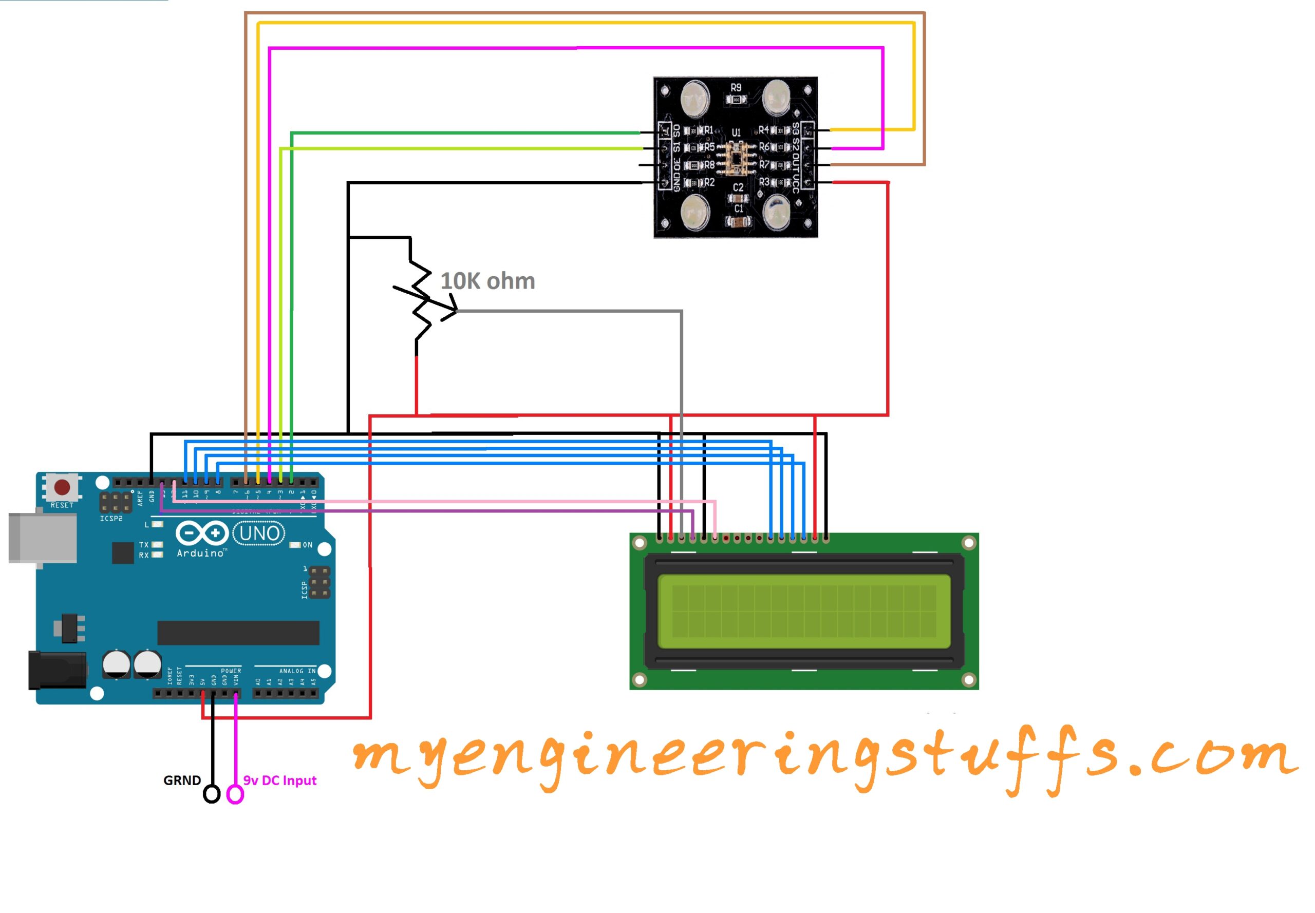
Circuit diagram

Follow the circuit diagram and the table below to connect each every connection correctly.
Connection of TSC3200 with Arduino UNO
| TSC3200 color sensor | Arduino UNO |
| S0, S1, S2 and S3 | D2, D3, D4, and D5 respectively |
| OUT | D6 |
| VCC and GND | VCC and GND common |
Connection of LCD with Arduino UNO
| 16×2 LCD | Arduino UNO |
| RS | 13 |
| RW | GRND |
| E | 12 |
| D7, D6, D5, D4 | 8, 9, 10, and 11 respectively |
Power Supply
While looking at the circuit diagram a power input is given to Arduino UNO at pin GND and VIN of 9v DC. Please make sure that you are providing 9v DC only or you may damage your Arduino UNO board.
Code Explanation
In this code, we are using some pre define values of RGB, these values are written after knowing the particular object color in front of the TSC3200 color sensor. So, make sure to write your own values for R, G and B. Include the libraries we need to use in our code.
Declare an object variable of the constructor of the LiquidCrystal library using pins.
#include <LiquidCrystal.h>
LiquidCrystal lcd(13, 12, 11, 10, 9, 8);
The below macros are defined for the Arduino UNO pins.
#define S0 2
#define S1 3
#define S2 4
#define S3 5
#define sensorOut 6
The below variables are declared to store the values of R, G, and B.
int Rfre = 0,Gfre = 0,Bfre = 0;The setup function includes the initialization of LCD declaring S0, S1, S2, and S3 as output pins, sensor out as input pins, and setting the frequency scaling percentage to 20% by setting the value of S0 to HIGH and S1 to LOW.
lcd.begin(16,2); // initialize the LCD with 16x2 LCD
pinMode(S0, OUTPUT);
pinMode(S1, OUTPUT);
pinMode(S2, OUTPUT);
pinMode(S3, OUTPUT);
pinMode(sensorOut, INPUT);
// Setting frequency-scaling to 20%
digitalWrite(S0,HIGH);
digitalWrite(S1,LOW);
Full source code
#include <LiquidCrystal.h>
// initialize the library with the numbers of the interface pins
LiquidCrystal lcd(13, 12, 11, 10, 9, 8);
#define S0 2
#define S1 3
#define S2 4
#define S3 5
#define sensorOut 6
int Rfre = 0,Gfre = 0,Bfre = 0;

void setup()
{
  lcd.begin(16,2); // initialize the LCD with 16x2 LCD
  pinMode(S0, OUTPUT);
  pinMode(S1, OUTPUT);
  pinMode(S2, OUTPUT);
  pinMode(S3, OUTPUT);
  pinMode(sensorOut, INPUT);
  // Setting frequency-scaling to 20%
  digitalWrite(S0,HIGH);
  digitalWrite(S1,LOW);
  lcd.setCursor(0,0);
  lcd.print("COLOUR DETECTION");
  delay(4000);
}

void loop() {
  // Setting red filtered photodiodes to be read
  digitalWrite(S2,LOW);
  digitalWrite(S3,LOW);
  // Reading the output frequency
  Rfre = pulseIn(sensorOut, LOW);
  delay(100);
  // Setting Green filtered photodiodes to be read
  digitalWrite(S2,HIGH);
  digitalWrite(S3,HIGH);
  // Reading the output frequency
  Gfre = pulseIn(sensorOut, LOW);
  delay(100);
  // Setting Blue filtered photodiodes to be read
  digitalWrite(S2,LOW);
  digitalWrite(S3,HIGH);
  // Reading the output frequency
  Bfre = pulseIn(sensorOut, LOW);
  delay(100);
  lcd.setCursor(0,1);
  lcd.print("                ");
if((Rfre>=24 && Rfre<=25)&&(Gfre>=20 && Gfre<=21)&&(Bfre>=8 && Bfre<=9)){
  lcd.setCursor(0,0);
  lcd.print("COLOUR DETECTED ");
  lcd.setCursor(0,1);
  lcd.print("  LIGHT GREEN   ");//printing name
  delay(2500);
}
if((Rfre>=20 && Rfre<=21)&&(Gfre>=20 && Gfre<=21)&&(Bfre>=6 && Bfre<=7)){
  lcd.setCursor(0,0);
  lcd.print("COLOUR DETECTED ");
  lcd.setCursor(0,1);
  lcd.print("   LIGHT BLUE   ");//printing name
  delay(2500);
}
if((Rfre>=8 && Rfre<=9)&&(Gfre>=11 && Gfre<=12)&&(Bfre>=4 && Bfre<=5)){
  lcd.setCursor(0,0);
  lcd.print("COLOUR DETECTED ");
  lcd.setCursor(0,1);
  lcd.print("     YELLOW    ");//printing name
  delay(2500);
}
if((Rfre>=31 && Rfre<=32)&&(Gfre>=33 && Gfre<=34)&&(Bfre>=10 && Bfre<=11)){
  lcd.setCursor(0,0);
  lcd.print("COLOUR DETECTED ");
  lcd.setCursor(0,1);
  lcd.print("  DARK  GREEN   ");//printing name
  delay(2500);
}
if((Rfre>=11 && Rfre<=12)&&(Gfre>=30 && Gfre<=31)&&(Bfre>=5 && Bfre<=7)){
  lcd.setCursor(0,0);
  lcd.print("COLOUR DETECTED ");
  lcd.setCursor(0,1);
  lcd.print("      RED       ");//printing name
  delay(2500);
}
if((Rfre>=8 && Rfre<=9)&&(Gfre>=24 && Gfre<=25)&&(Bfre>=5 && Bfre<=6)){
  lcd.setCursor(0,0);
  lcd.print("COLOUR DETECTED ");
  lcd.setCursor(0,1);
  lcd.print("      PINK      ");//printing name
  delay(2500);
}
if((Rfre>=6 && Rfre<=7)&&(Gfre>=18 && Gfre<=19)&&(Bfre>=4 && Bfre<=5)){
  lcd.setCursor(0,0);
  lcd.print("COLOUR DETECTED ");
  lcd.setCursor(0,1);
  lcd.print("     ORAGNE     ");//printing name
  delay(2500);
}
if((Rfre>=23 && Rfre<=24)&&(Gfre>=37 && Gfre<=38)&&(Bfre>=9 && Bfre<=10)){
  lcd.setCursor(0,0);
  lcd.print("COLOUR DETECTED ");
  lcd.setCursor(0,1);
  lcd.print("   DARK BROWN   ");//printing name
  delay(2500);
}
else{
  lcd.setCursor(0,0);
  lcd.print("COLOUR DETECTION");
  lcd.setCursor(0,1);
  lcd.print("R");//printing name
  lcd.print(Rfre);//printing RED color frequency
  lcd.print("  ");
  lcd.setCursor(6,1);
  lcd.print("G");//printing name
  lcd.print(Gfre);//printing RED color frequency
  lcd.print("  ");
  lcd.setCursor(12,1);
  lcd.print("B");//printing name
  lcd.print(Bfre);//printing RED color frequency
  lcd.println("  ");
}
}