
Table of Contents
Introduction
In the Raspberry Pi Pico tutorial series, now this is also another interfacing tutorial and we hope you will like. In this tutorial we will learn how to control a servo motor using Raspberry Pi Pico board. Here we will use Pulse Width Modulation to control the servo motor.
Pulse Width Modulation
Pulse Width Modulation (PWM) is a technique used in controlling the amount of power delivered to an electrical device and it can be achived by rapidly switching a power source on and off. And due to this it creates a series of pulses with varying widths as we are changing the time period of the pulse by rapidly switching is on and off, that effectively control the average power delivered to the device. PWM is used for controlling speed of motors, intensity of lights, and etc.
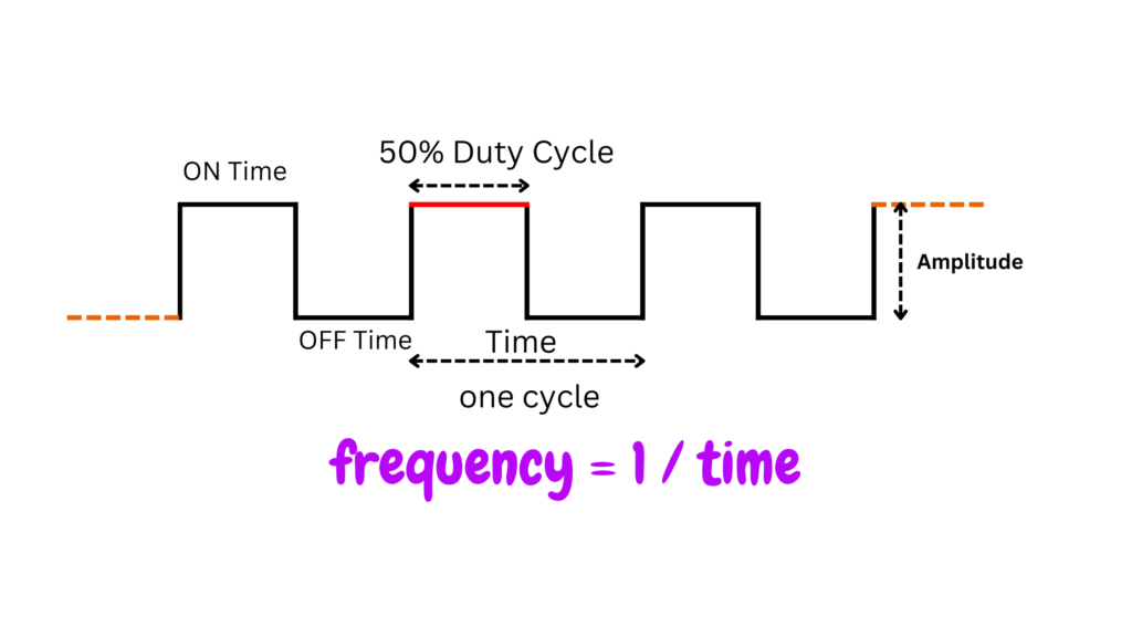
The above figure demonstrates a square wave signal assuming that a digital signal having an amplitude of 5v. One duty cycle is a complete pulse, this means that the ON time and the OFF time is a 100% of a cycle. Now we need to control the ON time of the pulse, by varying the percentage of ON time from 0% to 100% we can control the width of the pulse.
In a normal condition a microcontroller can produce an 500Hz digital signals and this high frequency signal are generally used to control high frequency switching device like inverter, converter etc. But in our case, servo motor needs only 50Hz of signal (Please read Datasheet). So, we need to produce 50Hz of signal it means frequency is also controllable from microcontroller.
Hardware Requirements
Disclaimer: It may contains Amazon affiliate links. which means I can get a small commission on the sale. This might be your indirect help to me. Thank You 🙏- Raspberry Pi Pico Board (HERE)
- Micro-USB Cable (HERE)
- Servo Motor (HERE)
- Small Breadboard (HERE)
- Connecting Wires (HERE)
Software Requirements
About Servo Motor
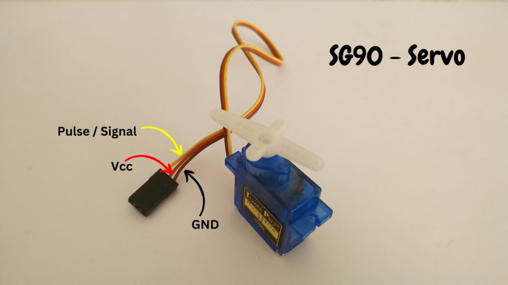
Servo motors are very high torque motor with a feedback mechanism controlled via a potentiometer. This motor is a low cost motor and can be used various robotic purpose. This motor is also very popular in hobbyist community. This can be used to give an angle to a particular object mounted over it or fixed with it. Just like controlling the flap of RC plane and control the direction and can be used to steer the wheel of an robot.
This motor have three pins VCC, GND, and SIGNAL. As per the name VCC and GND is the power input to the motor, here we will connect 3.3v and common ground respectively. And SIGNAL pin is the main controlling pin which is fed with the PWM signal. So, from Raspberry Pi Pico board we will generate the desired PWM signal and fed to this SIGNAL pin of servo to control the angle of horn of the motor.
Circuit Diagram
Circuit Explanation
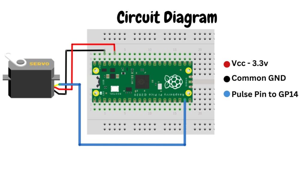
The circuit diagram is very simple, follow the circuit diagram and build your circuit correctly.
SG90 Servo Motor: As we know the motor consists of three wires. In which the RED is connected to the 3.3v, and the BLACK wire which is ground pin is connected to the ground pin, and the YELLOW or ORANGE is the SIGNAL pin of the servo is connected to the GP14 pin of the Raspberry Pi Pico board.
VSYS is the system voltage here you can supply external 5v input also and GND is the common ground of the board.
Controlling Servo Motor Using Raspberry Pi Pico board
Programming in MicroPython. Here we have used duty_u16 to control the angle in degrees by providing time duration in microseconds instead of providing direct angle to the servo. The servo angle 0 to 180 degree represents 1000 to 9000 units microseconds.
This piece of code is used to import the necessary library files
from machine import Pin,PWM
import utime
The below code is used to set the servo horn in an angle.
def setServoAngle (position):
    pwmPin.duty_u16(position)
    utime.sleep(0.01)
Video Tutorial
Download Source Code
Download the complete source code: click here