Table of Contents
Introduction
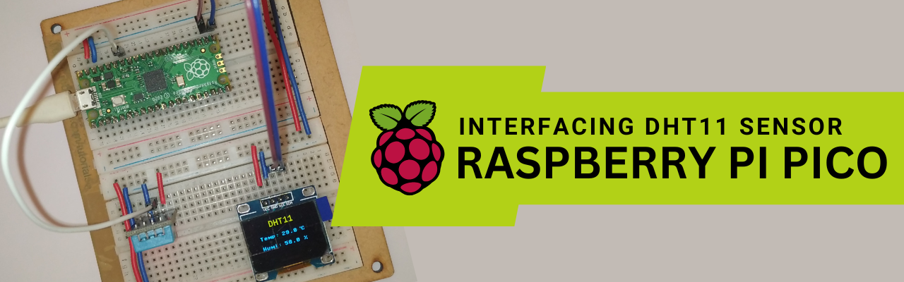
In this tutorial, we will know how to integrate the DHT11 humidity and temperature sensor with raspberry pi pico. At first, we will write a MycroPython code for the DHT11 sensor and integrate it with raspberry pi pico and see the data in the serial monitor. And then we will use a 0.96″ I2C OLED to display the same humidity and temperature data on the display.
DHT11 is a low-cost humidity and temperature digital sensor. DHT11 sensor is made up of with capacitive humidity and resistive temperature sensor inbuilt. This sensor is very easy to integrate with any of the microcontrollers like AVR ATMEGA16, Arduino, or Raspberry Pi Pico with any of the digital input pins.
This post is your step-by-step guide which will explain to you how to integrate and get the humidity and temperature data from the DHT11 sensor and display the data on a 0.96″ I2C OLED display.
Hardware Requirements
Disclaimer: It may contains Amazon affiliate links. which means I can get a small commission on the sale. This might be your indirect help to me. Thank You 🙏- Raspberry Pi Pico (HERE)
- Micro USB cable (HERE)
- 0.96″ I2C OLED Display (HERE)
- DHT11 Sensor (HERE)
- Connecting Wires (HERE)
- Small Breadboard (HERE)
Software Requirements
- Thonny IDE (Download HERE)
- DHT11 library code. (Download HERE)
- OLED display library code.
- The main code
About DHT11 Humidity & Temperature Sensor
DHT11 is a low-cost humidity and temperature sensor and uses a single-wire digital interface. Basically, it uses a capacitive humidity sensor and a thermistor to measure the temperature of the surrounding air. It can measure a temperature range of about 3.3 to 5 volts which is 0 to 50 degrees C with an accuracy of 2 degrees C and humidity of about 20% to 80% with an accuracy of 5%. The sensor makes use of single-wire communication which makes the sensor easy to interface with any of the microcontrollers.
DHT11 has four pins known as VCC, GND, and DATA, and the fourth pin is not connected. So, the fourth pin was left unconnected.
In the local market, you can get a bare sensor with four pins and a sensor module. You can use any of the types, leaving the fourth pin unconnected. And make sure when you use a bare sensor you need to connect a pull-up resistor of 4.7K ohm at its DATA pin.

The issue with this sensor is, it updates the sensor data once every 2 seconds. This means you will get 2 seconds of old sensor data.
Block Diagram & Explanation
The below block diagram is for the integration of the DHT11 sensor & Raspberry Pi Pico. Raspberry pi pico will fetch the data from the DHT11 sensor and process it and again it will send the display to display the data as per our requirement.

Circuit Diagram & Explanation
Follow the circuit diagram and build your circuit.

DHT11: The sensor DATA pin is connected to pin number GP28 of the Raspberry Pi Pico board. And the VCC and GND pin of the sensor is connected to the VSYS and GND of the Raspberry Pi Pico board respectively.
OLED Display: Connect the SCL and SDA pin of the display to the Raspberry Pi Pico GP17 and GP16 respectively. And the VCC and GND pin of the sensor is connected to the VSYS and GND of the Raspberry Pi Pico board respectively.
VSYS is the system voltage here you can supply external 5v input also and GND is the common ground of the board.

Source Code Explanation
MicroPython Code: The code we are using here is a composition of mainly three parts.
- DHT11 library code. (Download HERE)
- OLED display library code
- SSD1306 library code
- The main code
DHT11 Library Code: (dht.py)
Download the code from the given location, and extract the files if necessary. Now create a new file in Thonny IDE then copy the code of the dht.txt file and paste it into the new file. And save it as dht.py in the Raspberry Pi Pico board. This is the DHT library file.
The OLED library code: (oled need to install from Thonny IDE)
To install oled library follow the steps. In Thonny IDE go to Tools-> Manage Packages-> search “oled” for the library find the “micropython-oled” library from the search items by the author: Yeison Cardona and you can find an Install button below, just click and install it. It will be installed inside the Raspberry Pi Pico. So, no need to check, It will work.
SSD1306 library code:(ssd1306.py)
Now create a new file in Thonny IDE and open the ssd1306.txt file and copy the code to the new file and save it as a ssd1306.py file in the Raspberry Pi Pico board. This is the OLED library file.
Main Code: (main.py)
So, this is the final code that is responsible for the sensor data fetching and displaying the data to the OLED display. Now create one more file in the Thonny IDE and copy/paste the code given in the download section as mainCode.txt and save it as a main.py file in the Raspberry Pi Pico board.
Why the main.py file name?
You can give any name to the file but when running the code from Thonny IDE by clicking the green button it will run once. But when we give the name main.py to the file, the Raspberry Pi Pico board will automatically detect and run the code whenever you want. You can say that this is a process of AutoStart system.
Video Tutorial
Download Source Code
Download the complete source code: click here