Table of Contents
Introduction
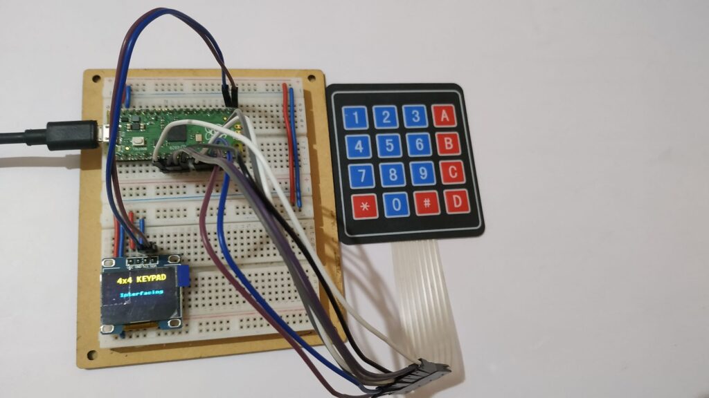
In this tutorial we will interface a 4×4 membrane keypad with raspberry pi pico board and build an password protected authentication system and display it on an 0.96 inch OLED display.
We will start with the integration process in which we will learn about the 4×4 keypad, SSD1306 OLED display and then we will complete the project.
The system checks the key pressed rapidly and stores the data in an array after the desired key press, the system will check with the actual hard coded password and authenticate the user or denied the user.
Hardware Requirements
Disclaimer: It may contains Amazon affiliate links. which means I can get a small commission on the sale. This might be your indirect help to me. Thank You 🙏- Raspberry Pi Pico Board (HERE)
- Micro-USB Cable (HERE)
- 4×4 Membrane Keypad (HERE)
- Small Breadboard (HERE)
- Connecting Wires (HERE)
Software Requirements
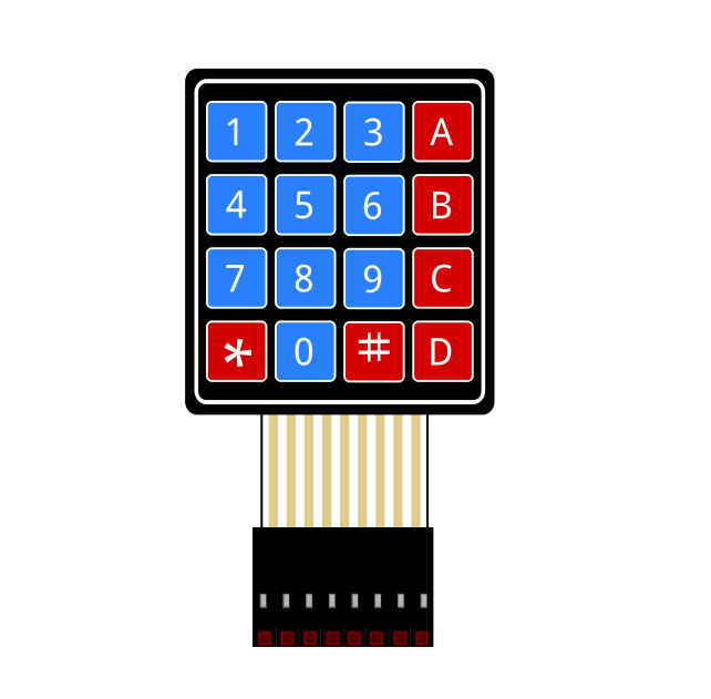
4×4 Membrane Keypad
4×4 Keypad is an input device which can provide 16 key combination inputs to the microcontroller. And it uses only 8 general purpose inputs and outputs pins. It comes with a thin membrane which makes it very flexible and compact. The keys are divided into rows and columns. These switches are connected with a conductive trace with top and bottom conductive plates, whenever any key is press any of the conductive trace get connected and microcontroller detects this combination and get the key value as per our keys settings. In the code section we will assign the key value as per our requirements.
Basically it is combined with two layer, upper layer with the key values printed on it and have conductive plates with conductive traces and in the lower layer with a back panel with conductive plates just below the printed key. So, whenever a key is pressed the upper conductive plate get connected to the layer conductive plate and making a close connection, so then microcontroller detects this connection and print the value.
SSD1306 OLED Display
The Organic Light Emitting Diode(OLED) is an 0.96 inch, 128×64 resolution display with thin multi layered organic film sandwich between anode and cathode. It is based on self emitting diode technology and it does not require any back light like LCD. This module is interfaced using SPI communication that requires only two wire of communication. This display can be interfaced with any microcontroller using SPI/IIC communication protocols.
| SSD1306 OLED | Description |
| VCC | 3.3v – 5v |
| GND | Common Ground |
| SCK | Serial Clock |
| SDA | Serial Data |
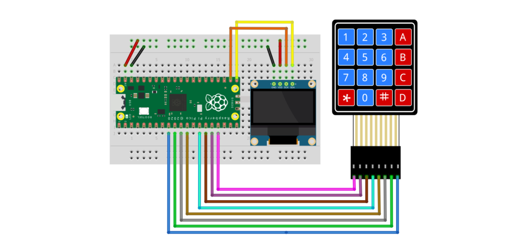
Circuit Diagram
Circuit Explanation
Follow the circuit diagram and build your circuit correctly.
HC-SR04: The sensor TRIG pin is connected to pin number GP19 and the ECHO pin is connected to pin number GP18 of the Raspberry Pi Pico board. And the VCC and GND pin of the sensor is connected to the VSYS and GND of the Raspberry Pi Pico board respectively.
4×4 Membrane Keypad: Starting from right to left of the keypad the pinout is shown in the keypad section. Please the keypad section for the pin number of keypad and the below table to complete the circuit.
| 4×4 Membrane Keypad | Raspberry Pi Pico |
| COL1 | GP6 |
| COL2 | GP7 |
| COL3 | GP8 |
| COL4 | GP9 |
| ROW1 | GP10 |
| ROW2 | GP11 |
| ROW3 | GP12 |
| ROW4 | GP13 |
OLED Display: Connect the SCL and SDA pin of the display to the Raspberry Pi Pico GP17 and GP16 respectively. And the VCC and GND pin of the sensor is connected to the VSYS and GND of the Raspberry Pi Pico board respectively.
VSYS is the system voltage here you can supply external 5v input also and GND is the common ground of the board.
Source Code Explanation
MicroPython Code: The code we are using here is a composition of mainly three parts.
- OLED display library code.
- SSD1306 library (Download HERE)
- The main code
The OLED library code: (oled need to install from Thonny IDE)
To install oled library follow the steps. In Thonny IDE go to Tools-> Manage Packages-> search “oled” for the library find the “micropython-oled” library from the search items by the author: Yeison Cardona and you can find an Install button below, just click and install it. It will be installed inside the Raspberry Pi Pico. So, no need to check, It will work.
SSD1306 display library code:(ssd1306.py)
Now create a new file in Thonny IDE and open the ssd1306.txt file and copy the code to the new file and save it as a ssd1306.py file in the Raspberry Pi Pico board. This is the SSD1306 library file.
Main Code: (main.py)
So, this is the final code that is responsible for the sensor data fetching and displaying the data to the OLED display. Now create one more file in the Thonny IDE and copy/paste the code given in the download section as mainCode.txt and save it as a main.py file in the Raspberry Pi Pico board.
Why the main.py file name?
You can give any name to the file but when running the code from Thonny IDE by clicking the green button it will run once. But when we give the name main.py to the file, the Raspberry Pi Pico board will automatically detect and run the code whenever you want. You can say that this is a process of AutoStart the system.
Video Tutorial
Download Source Code
Download the complete source code: click here