Table of Contents
Introduction
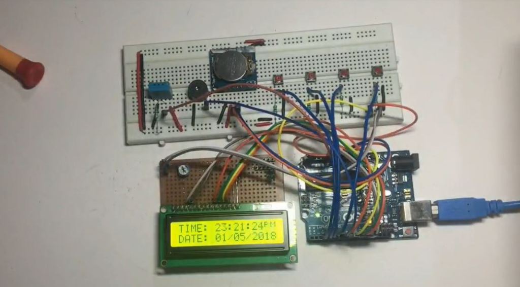
This project is built with Arduino UNO as the brain, a DS1307 RTC module to keep track of the time and a DHT11 sensor to get the room temperature and humidity. DS1307 is attached with an external button cell which keeps the time tickling after even the power goes off. And this is the reason why the time is accurate after being powered off in any digital system that tracks records or logs data with time.
This system is having four modes of operation. (Please refer to the circuit diagram strictly recommended)
Working of Project
This project works in four different modes of operations. Here we will see each and every modes of operation. We will start with the default mode and then we will change the mode and work on every mode.
Default Mode
This is the main screen and the default screen, from here we will navigate to other screen and return back to this screen. You may call this the default of the initial screen which displays time, temperature, and humidity by default. And after completing any of the other mode tasks it redirects to this screen. So, this is the default mode or screen.

Alarm Mode
In this mode, the user can set the alarm. Press SW4 to change the mode to SET ALARM. Then press SW1 to change the position of the cursor. Every time you press SW1 it will change the position from the hour to the minute, to the second, and then exit. If you want to change the hour change it directly as it is in the hour by default. Press SW2 to increase the value of that position and SW3 to decrease the value. After setting the desired value press SW1 to exit the setting. Now you can see that you are at the main screen displaying the current time and alarm set time.

Timer Mode
In this mode, the user can set a countdown timer. Again pressing SW4 changes the mode and pressing SW3 will initialize the counter or timer. Pressing SW2 will change the minute section and increase the value. Now press SW4 to start the timer. And then after this, you can see it redirect to the main screen and the timer will start automatically. Press SW4 & SW2 simultaneously to exit from the mode.

Stopwatch Mode
In this mode, the user can start, pause, stop, and reset using this mode. Pressing SW4 will change the mode set to STOPWATCH. Pressing SW3 will initialize the stopwatch. Press SW1 to start, press SW2 to pause, and press SW3 to reset the stopwatch.

Hardware Requirements
Disclaimer: It may contains Amazon affiliate links. which means I can get a small commission on the sale. This might be your indirect help to me. Thank You 🙏- Arduino UNO (HERE)
- DHT11 sensor (HERE)
- RTC module-DC1307 (HERE)
- Alpha Numeric 16×2 LCD (HERE)
- 10K POT for LCD contrast (HERE)
- 5v Buzzer
- BC 547 transistor
- 1K ohm resisters -7pcs
- Push to ON switch-4pcs
- Voltage regulator -7805
- LED -5mm RED- 2pcs
Software Requirements
- Arduino IDE (You can download it from HERE)
- Arduino RTC Library
- LCD Library
- Wire Library
- EEPROM Library
- DHT Library (Download it from HERE)
- RTC-Lib Library (Download it from HERE)
Block Diagram

Circuit Diagram

Circuit Explanation
Power Supply Circuit
The whole system works on the 5v DC supply. You can use the external power supply as shown in the circuit diagram. The main purpose is to step down the 12v to 5v DC by using a 7805 voltage regulator which gives you an output of 5v DC. Pin 1 of 7805 is fed with the input voltage of 12v of the power supply and pin 2 of 7805 is a common ground that is connected to the GRND line of the entire circuit. Pin 3 of 7805 gives you the regulated 5v DC which further we will use in our project.
DS1307 RTC module
Please visit this article to know how to interface the DS1307 RTC module with Arduino UNO. As we know the RTC is powered with a built-in button cell which helps to track the real-time. Please refer to the below table.
| DS1307 RTC | Arduino UNO |
| SDA | A4 (SDA) |
| SCL | A5 (SCL) |
| VCC | 5v |
| GND | GND |
DHT11 Sensor
This is a single-wire communicating digital sensor which is packed with a capacitive humidity sensor and a thermistor that gives the temperature. Follow the below table of connections.
| DHT11 | Arduino UNO |
| PIN1 (VCC) | A0 |
| PIN2 (OUT) | 5v |
| PIN3 | NC |
| PIN4 (GND) | GND |
Alphanumeric 16×2 LCD
Please follow the below table and make the connection correctly.
| 16×2 LCD | Arduino UNO |
| RS | 13 |
| RW | GRND |
| E | 12 |
| D7,D6,D5,D4 | 8,9,10,11 respectively |
Switches Connection
Here we are using four 1K resistors to provide a default state to the PINs D6, D5, D4, and D3 and that is HIGH. This means we have connected the PINS to VCC through a 1K resistor. By doing this we are setting the PINS state to HIGH as a default value. And when the press the switch it goes to a LOW value and will be detected at the PIN hence we get to know the switch is being pressed. Follow the below table and connect the switches accordingly.
| SWITCHES | Arduino UNO |
| SW1 | D6 |
| SW2 | D5 |
| SW3 | D4 |
| SW4 | D3 |
Buzzer Connection
The buzzer is connected to PIN 7 of Arduino through a common emitter NPN transistor (BC547). The base of the BC547 is connected to a 1K ohm resistor and one end of the resistor is connected to PIN 7 of Arduino. The emitter of BC547 is connected to a common GND. The Collector of BC547 is connected to the negative terminal of the buzzer whereas the positive terminal of the buzzer is connected to a 5v DC supply.
How Circuit works:
When the circuit initializes it enters the default mode with some initial messages while fetching the current time, temperature and humidity. As soon as it enters it starts displaying the current time, temperature, and humidity on a 16×2 LCD.
Video Tutorial
Download Source Code
Download the complete source code: click here